ROBOTICS CAPSTONE PROJECT
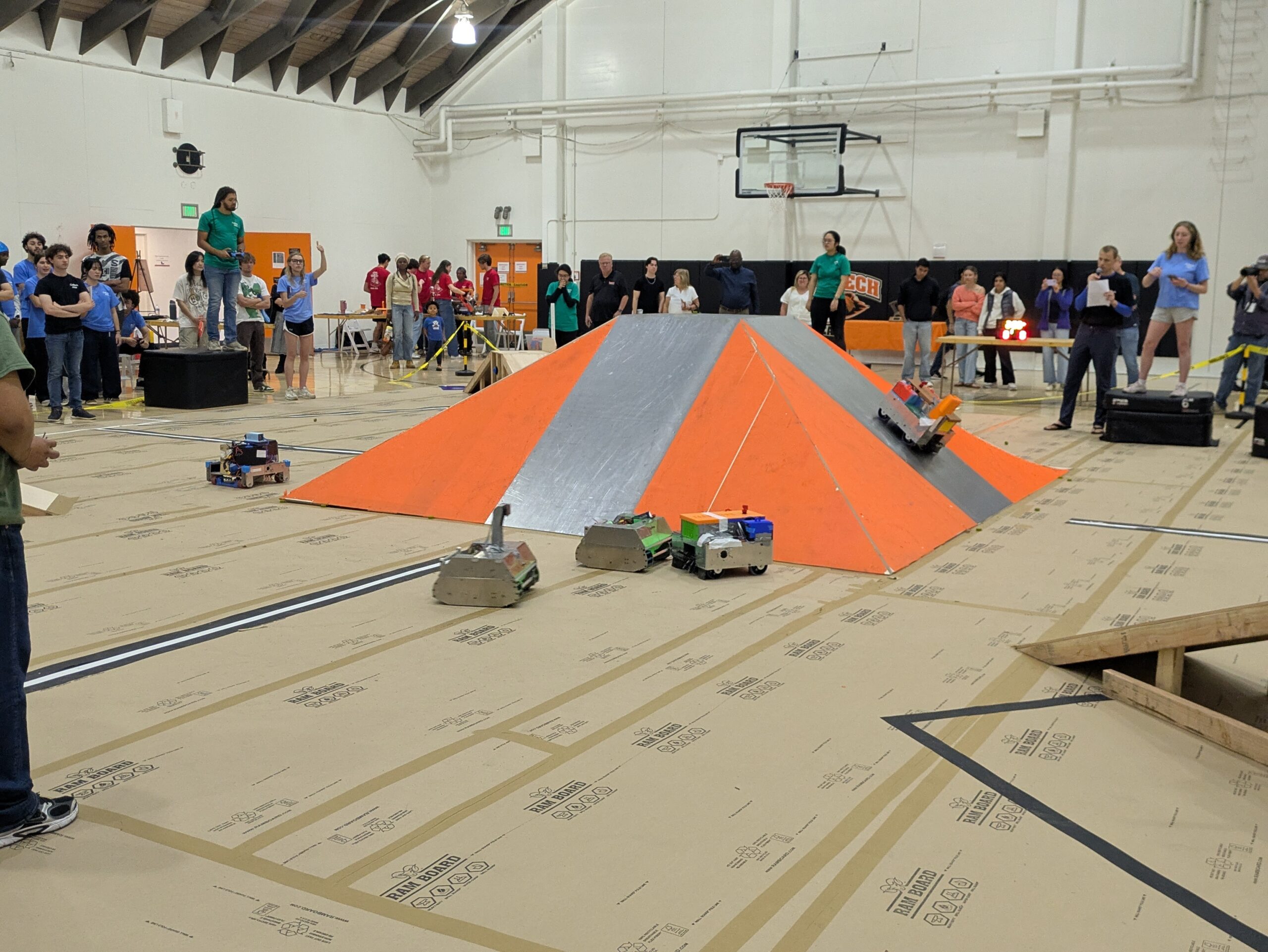
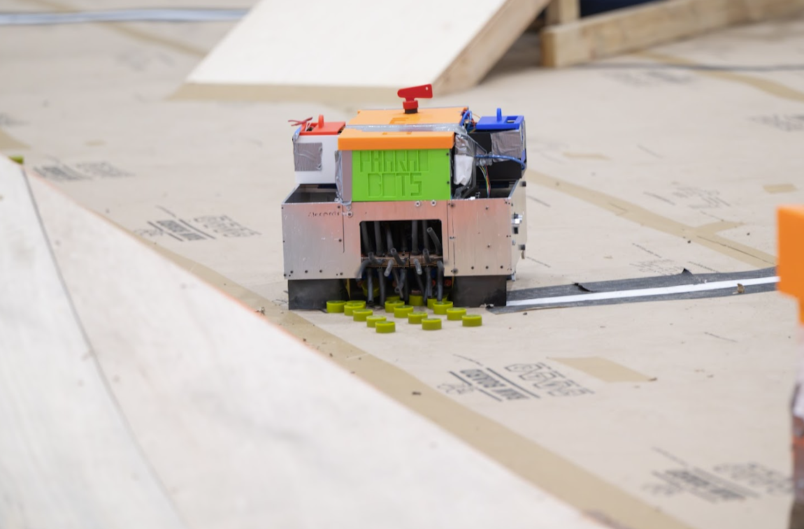
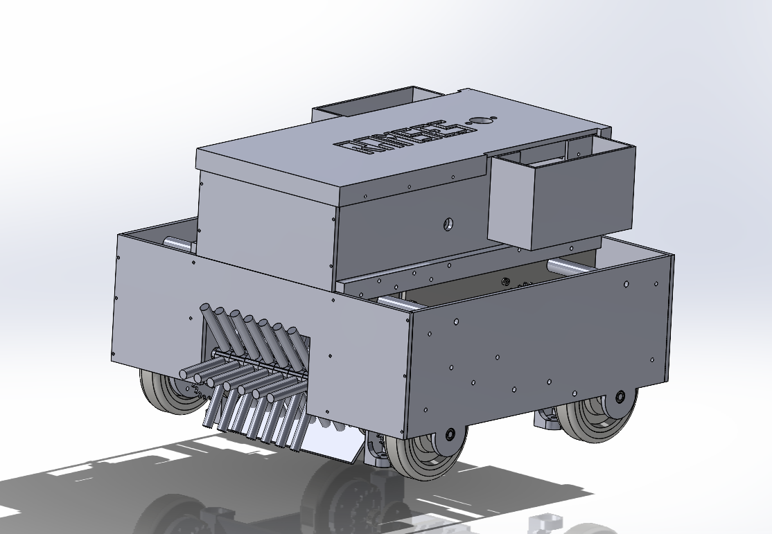
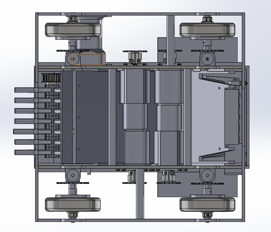
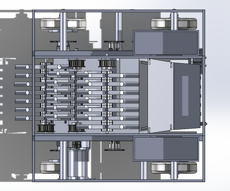
Most recently, I created two robots with a team of 6 other people in a robotics competition for a 20-week senior capstone project (ME 72). This challenge involves designing two RC-controlled robotic cars capable of picking up 3D-printed pellets and ping pong balls and summiting a steel-coated pyramid with an incline angle of 37° to deposit pellets into a small hole. Three teams (with two robots each, totaling 6 robots per match) competed at a time. The first 30 seconds of competition involved line-following to press a button first and pick up additional pellets autonomously, followed by a 4-minute teleoperated period. To make the competition more interesting, the robots were allowed to engage in combat with one another, which caused all teams to consider durability and strength when designing the robots. A tight budget of $1,200 was given to each team to work under.
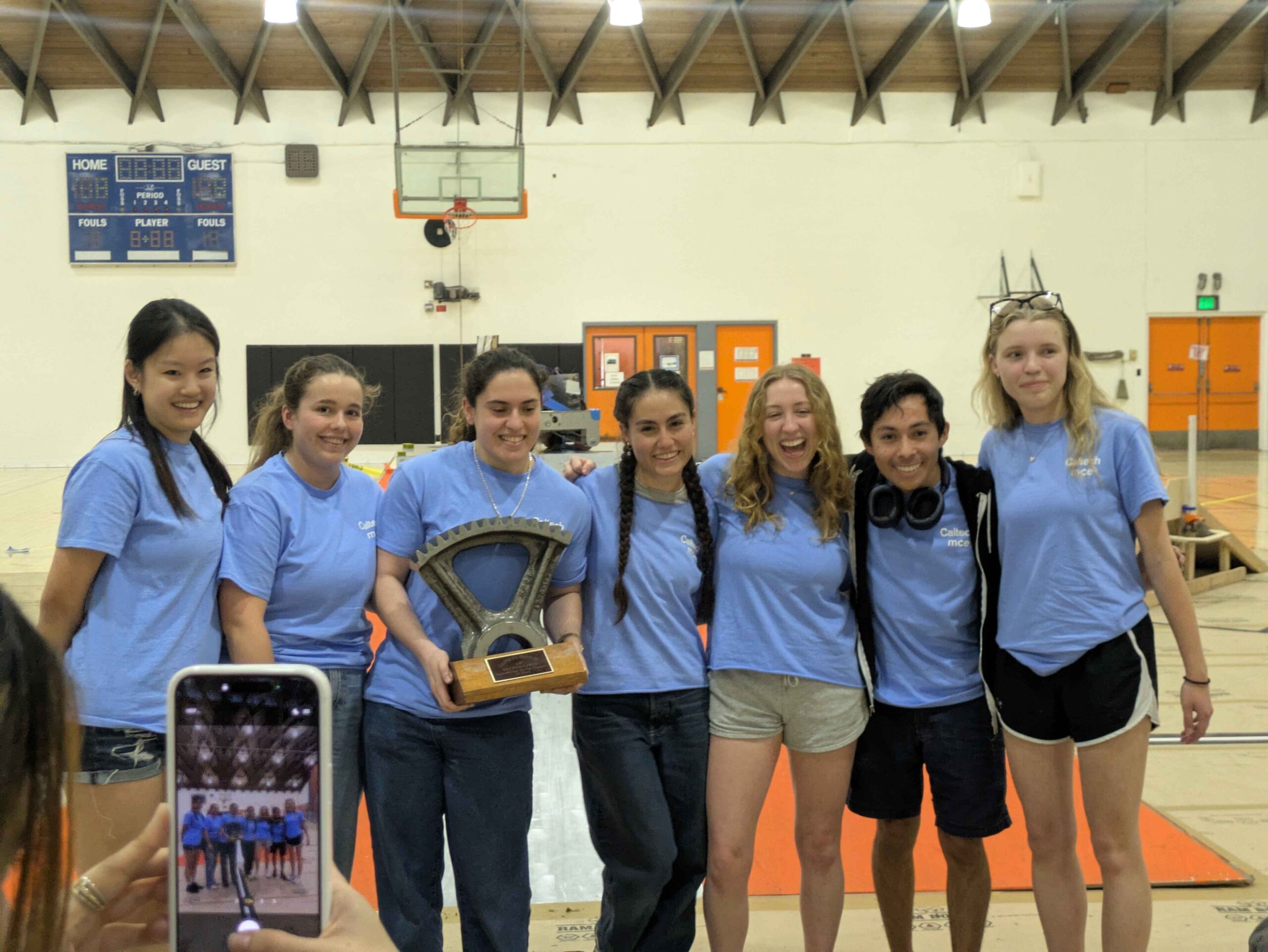
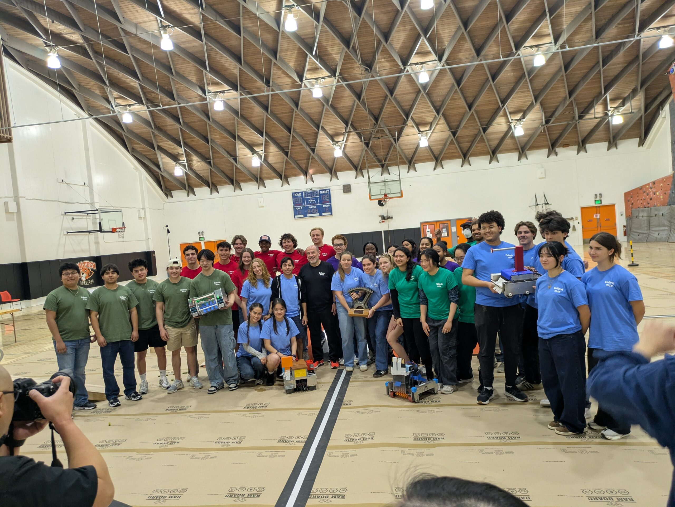
At the end of the competition, my team (Pharobots) placed first and earned the highest score of any match against all other teams. The competition was recorded and streamed briefly on local news and an article reporting the competition can be found here.
Over the course of this project, I contributed across the full development cycle of the robots, beginning with early system design and eventually evolving into a technical leadership role during the second half of the project. In the first ten weeks of the project, I collaborated with my team to develop the overall game strategy and mechanical design, including drivetrain design, intake design, and motor selection. As we approached the PDR and CDR, I shifted my focus towards developing an electronics schematic which involved an Arduino, four RoboClaw motor controllers, and an additional small motor powered by a 12V lipo battery and additional AA battery pack. Through iterative prototyping, I configured the RC control system and developed a reliable control setup that enabled intuitive driving, turning, and climbing which led to a successful mobility demo at the halfway point of the course. Videos of this demo are shown below.
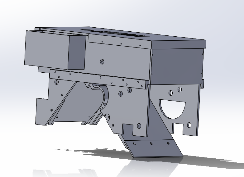
One of our biggest weaknesses approaching the mobility demo was climbing the pyramid due to too small of a normal force on the pyramid. To remedy this issue, I designed and prototyped mounts for small magnets that would sit with a very low clearance from the ground in order to increase the effective normal force of the robot without changing the weight much at the cost of speed.
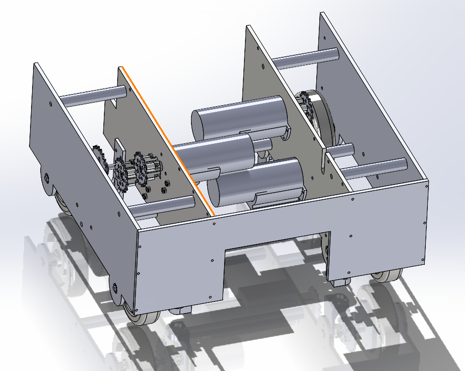
In the second term, my role on the team shifted toward mechanical design and project leadership as the system matured. I assumed responsibility for maintaining and restructuring the CAD assembly using SolidWorks, resolving accumulated design issues and rebuilding major subassemblies to increase better cross-subteam communication. I redesigned the drivetrain walls and front structure to improve robustness and integration by having space to protect the intake and wheels from collisions, and machined key components such as front plates, shafts, churros, and motor mounts. I became extremely comfortable using the manual mill and lathe and gained a lot of experience with 3D printing. I also led multiple design iterations of the magnet mounts based on testing results and ultimately contributed to a redesign of the intake using new motors. Working closely with teammates, I helped redesign the upper assembly to improve wire management and accessibility, and I consistently oversaw subsystem assembly to ensure alignment between design intent and physical implementation. Through this process, I transitioned to a technical lead role on the team, guiding design and machining decisions, organizing frequent testing, and making sure of proper system integration.
AUTONOMOUS LINE-FOLLOWING ROBOT
I am in the process of building and programming an autonomous small robotic car capable of exploring an unknown map using IR sensors and Ultrasound sensors with a partner. The maps consist of black tape with intersections between multiple paths, potholes in the tape, additional pieces of tape, dead ends, and blockages (cardboard boxes). The robot uses a raspberry Pi with a portable battery to control two small servo motors for the driving wheels with a front ball caster wheel, handle logic from 3 IR sensors at the front of the robot, and 3 Ultra sound sensors pointing towards the left, right, and front sides of the robot up to 3.3 meters. We assembled the robot and created a robust program to allow the robot to line-follow, turn at intersections, and autonomously make decisions on exploring the map, utilizing Dijkstra’s algorithm for the most efficient travel path. We also programmed the robot to respond to object detection using the Ultrasound sensors to avoid obstacles and follow walls. At the end of the quarter, the robot will compete in a challenge involving exploring and travel path optimization against other robots.
We have well-documented this process through weekly reports including flowcharts, pseudocode, and code API, updating our code each week to a GitHub repository.
Below are sample videos of the robot’s behaviors. In the left video, the robot follows a wall using the ultrasound detectors at a nominal distance of 30 cm. In the middle video, the robot follows the wall but starts a bit too close to the wall but corrects itself. In the third video, the robot was programmed to respond to input from each of the sensors to drive straight without obstacles detected, and navigate around obstacles by turning, backing up, or stopping at a comfortable distance.
In the last video (sped up to get the point across faster), the robot is auto-exploring a new map. The visual pops up to show the empty grid and the growing map as the robot explores. Every time a robot detects an intersection, all the possible streets around the robot are visually indicated by line segments, where the different colors correspond to the state of these streets (gray = the street doesn’t exist, blue = the street exists but hasn’t been explored, green = the street connects to another intersection, and red = the street is a dead end). The user inputs the coordinates and direction of the robot before starting the exploration arbitrarily (not pictured in this video), but I happened to choose the origin point on the map poorly which is why one of the intersections on the map visualization was a bit cut off.
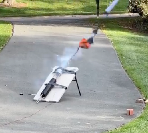
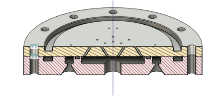
AMATEUR LIQUID ROCKET
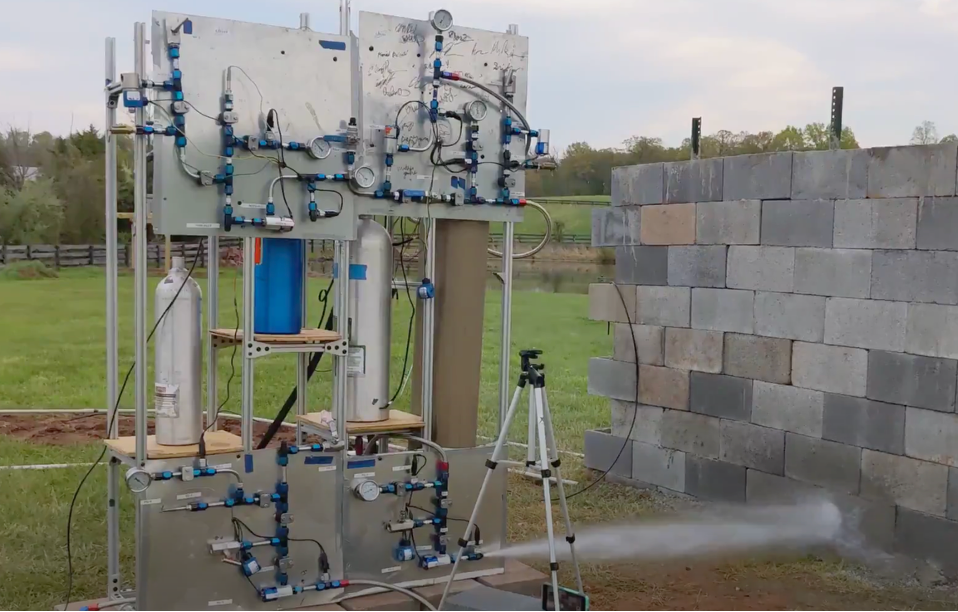
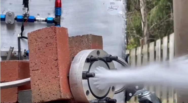
I led the engineering team to design, build, and test a bi-propellant liquid rocket. This was part of a group of amateur rocket-hobbyists called Project Caelus. Over the course of three years, we designed an entire engine, including the CAD of the injector, chamber, and nozzle using Fusion 360, the Piping & Instrumentation Diagram (P&ID), and the recovery system. We fabricated the injector and nozzle using a CNC machine, vertical drill press. I particularly took charge of the injector and nozzle design and testing, but also worked extensively on the plumbing including the design of the P&ID, assembly, and leak testing. We assembled a test stand to house the plumbing and ran multiple successful water cold flows of both propellant towers separately and together. We raised over $10,000 in funding and worked with NASA aerospace engineers and Aerojet Rocketdyne to complete PDR and CDRs of our rocket design.
Engine specifications:
– 2.5 kN thrust
– nitrous oxide & ethanol propellants
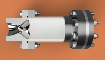
– self-impinging doublet injector
– deLaval nozzle
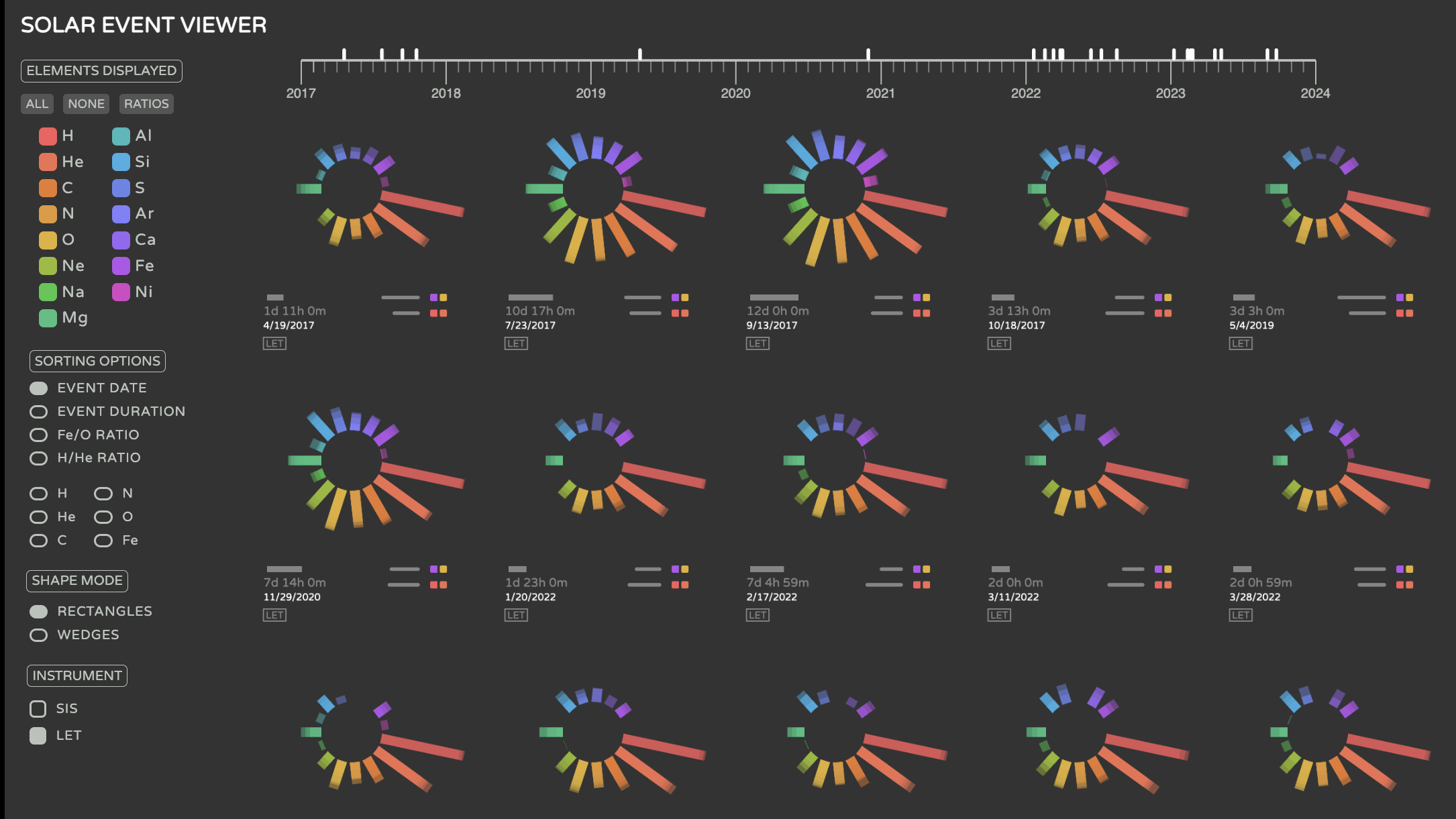
solar flare data visualization tool
I worked with a smaller version of Caltech’s Data to Discovery Program, where computer scientists and user design students are brought together to analyze a very large dataset that a research group at Caltech and/or JPL need assistance visualizing in order to find trends to inform research that would otherwise be impossible. I worked with Dr. Alan Labrador and Dr. Ashish Mahabal from the Cahill Center of Astrophysics at Caltech to design a web tool which visualizes solar flare data over the course of 7 years. The dataset included particle flux data over time steps for up to 15 elements across 8 energy bands and included data from both the STEREO and ACE solar probe missions. I reduced the dataset from a scale of ~1 TB to a few MB by creating summary JSON files which only extracted the parts of each solar flare event which were the most useful for the scientists’ research. Each solar flare event is represented by a circle with radiating rectangles/wedges which is intended to both artistically resemble the sun’s corona, where solar flares are visible, and create a visual pattern for the user to associate each element with. The length of each bar is scaled logarithmically to the particle flux intensity across a solar flare event peak, with each energy band stacked to still preserve the variation in particle flux intensity across energy bands. The tool allows users to easily toggle on and off elements to visualize, as well as sort by various features including the event date, event duration, and element ratios.
Since the summer, a more updated version of the tool can be found at this link: https://www.its.caltech.edu/~datavis/projects/solar-event-viewer/
I created this tool using JavaScript, HTML, Python, and CSS. I conducted user interviews and workflow reviews with the researchers and used p5.js to prototype the design. Throughout the entire project, I worked with the researchers to ensure that the visualizations were accurately representing the data in the way they intended. At the end of this report, I wrote a research paper which won the Joel and Marcella Bonsall SURF Technical Writing Prize. This tool is planned to be implemented as a part of NASA’s official ACE and STEREO mission websites and is continued to be used by Caltech’s heliophysics research group. We are in the process of waiting to hear if our paper has been accepted to IEEE Vis.
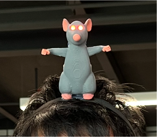
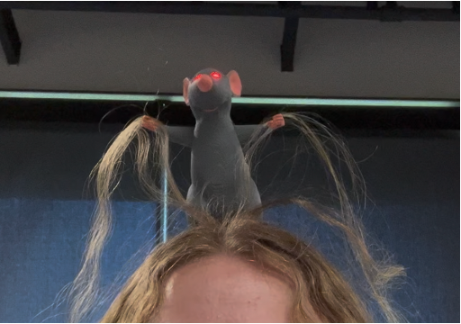
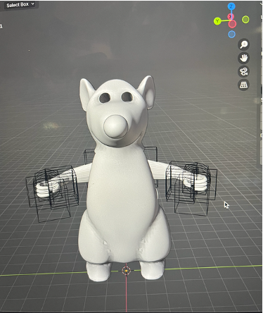
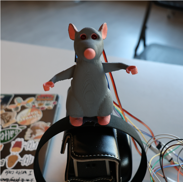
RATATOUILLE-INSPIRED ELECTRONIC HEADBAND
I worked with a two other Caltech students to create an electronically-controlled headband inspired by the movie Ratatouille. In the movie, a rat sits atop a chef’s head and pulls the chef’s hair to control his motions. I taught myself how to use Blender for this project and used it to make a model of the rat from scratch, which we 3D printed, painted, and secured to a headband. We programmed servo motors to move randomly using an Arduino Nano Every and attached them to the rat’s arms. The user’s hair can be threaded through the rat’s hands, which were designed to be closed loops to prevent hair from falling out. We also integrated two red LEDs for the eyes for humor. We documented this project through its entirety using Hackaday. Our project was selected to be presented at the LA Maker Faire + City of STEM event at USC, which included over 20,000 attendees.
ROBOTICS KINEMATICS PROJECT
In this project, I worked in a group of 2 other students to program the kinematics for ATLAS, a humanoid URDF from Boston Dynamics using ROS and python for a final class project. We had the option to make ATLAS complete whatever goal we wanted, so we decided to program the forward and reverse kinematics to make ATLAS start in an initial position and shoot a basketball into a hoop at a variety of different locations. We had 2.5 weeks to complete the project and had to write a final report and presentation, which are shown below.
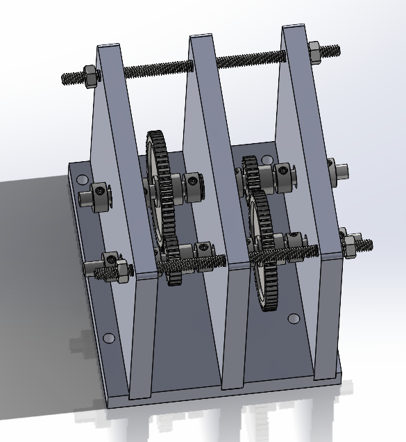
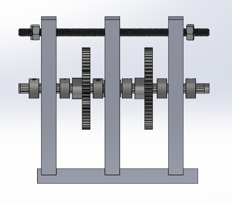
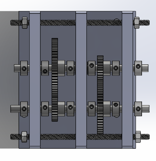
GEARBOX + competition
In this project, I worked with a team of 4 others to design and machine a gearbox capable of turning a bike wheel. We were given a motor and test bed, as well as a tight budget to purchase acrylic, gears, and shafts. Under these constraints, we were challenged to create a gearbox which would increase the motor’s torque and speed as much as possible in a competition against other students taking the class. We opted for plastic gears due to their cheap budget and weight reduction, and calculated a gear ratio based on our desired output speed and torque. We created a CAD of the gearbox in SolidWorks and machined the gearbox using a manual mill, lathe, and various other tools in Caltech’s machine shop. At the end of the competition, we ranked second overall, with the highest maximum speed achieved out of all of the teams.
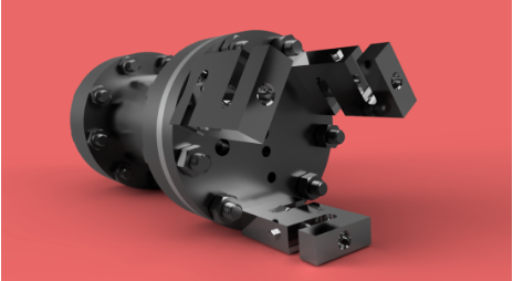
galvo-based fiber switcher
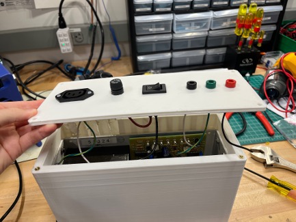
I worked with the Hutzler Group at Caltech to create a single-mode fiber switcher for precision measurement physics applications. One of the design-aspects of this project featured designing a casing for a high-voltage power supply unit which I created in CAD using OnShape and 3D printed. I soldered and assembled the box to contain the electronics and later performed tests which validated the power supply unit’s function.